Flagpole/Vertical Antennas...
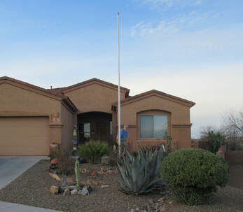
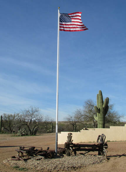
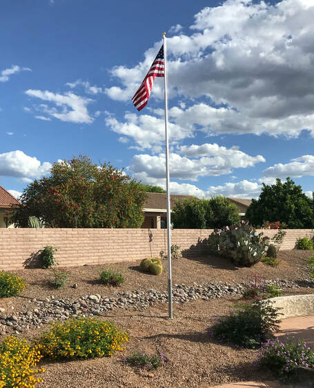
This is an end-fed flagpole antenna project in an HOA to avoid conflict with the anti-antenna rules and their enforcers.
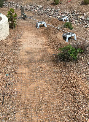
Before the project, I had a 20 foot FatSpectrum vertical on a DX engineering tilt-swivel mount: When I was operating, I popped it up, and when I was done operating, I popped it back down and laid it on the small gray stools that are in several of the pics.
The first phase was putting in about 120 square feet of fencing. The fencing is in rolls of 3 feet by 50 feet. The first two panels were 3 x 18.5 feet and 3 x 21 feet, buried barely under the surface of the gravel. They are about 30 degrees off being 180 degrees out of phase (think of a clock where the big hand is on the 6 and the little hand is on the 1). The third panel was 90 degrees out from the longer of the first two panels, forming something like a large K. I delayed putting in this one until after the flagpole replaced the original vertical antenna. All three are attached by ground wires to a DX Engineering ground plate mounted at the base of the flagpole.
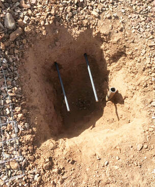
The next phase was digging the hole, pouring the concrete, and having the PVC base sunk into the concrete.
The PVC is the gray 3 inch PVC (less UV degradation over time). My intent was to bury it 30 inches into the ground and having 36 inches above ground. That failed because I ran into solid rock in the desired hole area, so I only got down 19 1/2 inches. To ensure better stability (thinking of high Arizona wind gusts that could topple the pole), I drove in rebar sections in the shape of a partial tic-tac-toe grid with the flagpole space in the middle, so that the concrete would be reinforced by rebar that went 12-18 inches off to the sides for better lateral stability. This pic shows the hole with some of the rebar installed. The steel pipe in the pick was the mounting bar I had for the previous antenna. I sawed it off with a hacksaw below the surface level because I couldn’t get it out of the ground. Off to the right of the picture you can see the top of the 7 foot ground rod that I had driven in for the previous antenna, and I kept it for grounding of the flagpole antenna.
The PVC is the gray 3 inch PVC (less UV degradation over time). My intent was to bury it 30 inches into the ground and having 36 inches above ground. That failed because I ran into solid rock in the desired hole area, so I only got down 19 1/2 inches. To ensure better stability (thinking of high Arizona wind gusts that could topple the pole), I drove in rebar sections in the shape of a partial tic-tac-toe grid with the flagpole space in the middle, so that the concrete would be reinforced by rebar that went 12-18 inches off to the sides for better lateral stability. This pic shows the hole with some of the rebar installed. The steel pipe in the pick was the mounting bar I had for the previous antenna. I sawed it off with a hacksaw below the surface level because I couldn’t get it out of the ground. Off to the right of the picture you can see the top of the 7 foot ground rod that I had driven in for the previous antenna, and I kept it for grounding of the flagpole antenna.
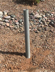
The PVC I used had to be sawed off for the 19 ½ inch hole. I painted it with flat gray non-metallic paint to make it look more like the flagpole. Non-metallic because I didn’t want any problems with having metal conductivity below ground level. As you can see from the other pics, I didn’t match the color of the paint very closely to the aluminum of the flagpole — I wish I had. This pic shows the PVC without the flagpole with dirt and gravel spread around it for the HOA inspection. At this point, the ground plate, the balun, the coax, and the buried fencing are not connected. This is just a cosmetic temporary solution to get me by the inspection.
I give special thanks to Ron, AA7RP, who advised me extensively throughout this entire phase, and he came over to help me pour the concrete and to make sure the PCV was perfectly vertical with a level as I poured the Quickcrete into the hole to set the PVC pipe.
I give special thanks to Ron, AA7RP, who advised me extensively throughout this entire phase, and he came over to help me pour the concrete and to make sure the PCV was perfectly vertical with a level as I poured the Quickcrete into the hole to set the PVC pipe.
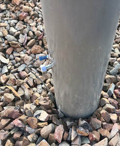
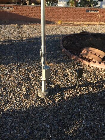
At that point, I assembled the flagpole and slid it into the PVC with a large bolt installed 6 inches above the ground to keep all metal above the surface. Here’s a pic that I took after the final process — it shows the bolt, but at this point in the sequence, the gray antenna lead wire was not there — it was strictly a flagpole and nothing else for inspection purposes.
After the successful HOA inspection, I proceeded with the rest.
After the successful HOA inspection, I proceeded with the rest.
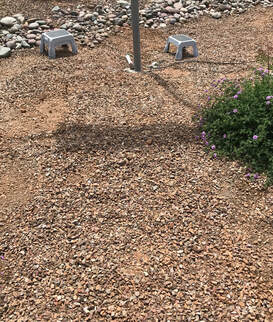
The next stage was to dig up the area around the flagpole and connect the fencing sections for the ground plane. I connected them directly to the DX Engineering ground plate, and connected that plate to the copper ground rod buried about 10 inches away. I then connected the coax from the shack to the ground plate, and then used a short coax to connect the ground plate to an MFJ 1:1 current balun. The output of the balun was a positive terminal that became an 8 inch gray (same spray paint ) lead that I attached about an inch above the large bolt in the previous picture by drilling a 1/2 inch hold through the PVC, then putting a number 8 steel metal screw and washer holding the lead directly into the aluminum flagpole through the 1/2 PVC hole.
At this point I disassembled the flagpole, and scuffed up the overlap areas in the pipe sections of the flagpole. Then I added an antioxidant paste from Home Depot in each overlap section, then reassembled. To ensure electrical connectivity, I drilled two holes and inserted steel screws through both overlapping pieces on each of the five sections of flagpole. (Again, all this was to comply with Ron’s expert advice on how they designed and installed the flagpole antenna for Tom Lang, K7VOA).
At this point I disassembled the flagpole, and scuffed up the overlap areas in the pipe sections of the flagpole. Then I added an antioxidant paste from Home Depot in each overlap section, then reassembled. To ensure electrical connectivity, I drilled two holes and inserted steel screws through both overlapping pieces on each of the five sections of flagpole. (Again, all this was to comply with Ron’s expert advice on how they designed and installed the flagpole antenna for Tom Lang, K7VOA).
How does it work?
It’s hard to tell if it is better or worse than my old configuration because the bands are never the same. However, I have had great signal reports from all over the US and Central America. I haven’t had a lot of time to explore contacts overseas like I had before, but just tuning through the bands, I seem to find that my reception of Europe and Asia are at least as good as before.
What would I have done differently?
Tom
K7AFA
It’s hard to tell if it is better or worse than my old configuration because the bands are never the same. However, I have had great signal reports from all over the US and Central America. I haven’t had a lot of time to explore contacts overseas like I had before, but just tuning through the bands, I seem to find that my reception of Europe and Asia are at least as good as before.
What would I have done differently?
- Don’t plant the fence sections until you have dug your hold and determined there is not a big rock in your path.
- Pick a paint color for the PVC that is closer to the color of the aluminum in the flagpole.
- Think through what you need to do with the flagpole at each step to minimize the number of times you need to put it up and take it down in the process.
Tom
K7AFA
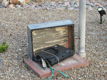
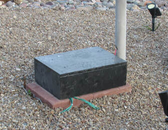
Ron's work on a vertical antenna... Overall View, Remote Tuner At Base and remote tuner covered
Drawing of K7VOA's flagpole vertical base. The counter poise is 64 square feet of galvanized fence centered on the mount and covered with gravel. The mast is 20 feet high.
What Antenna???
|
This is the base of N9MW's vertical. The insulator is 2 inch solid delrin reduced to fit into 2 inch aluminum tubing. The tubing goes up 8 feet then is epoxied to a MFJ telescoping mast with a wire inside to a height of 37 feet. The ground plane is 3 feet wide heavy gauge galvanized fence in an X pattern 50 feet and 25 feet then covered with the yard stone. A MFJ remote tuner is at the base reducing coax loss and shield currents.
|
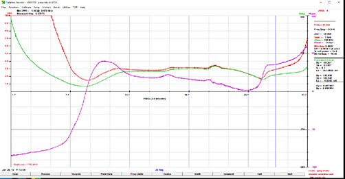
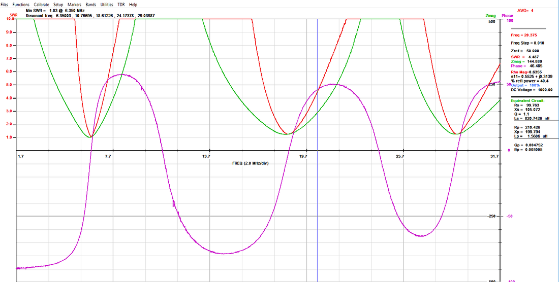
AIM scan of N9MW's vertical antenna. Red line is SWR
|
