GREEN VALLEY AMATEUR RADIO CLUB
  • Home
    • Repeater Info
    • OUR Web SDR
  • Projects
    • 13.8 Volt Load
    • Antenna Ideas
    • Antenna Construction Ideas
    • Dummy Load
    • Past Projects >
      • Organization
      • RFI Mitigation >
        • Direction Finders
      • 2 Meter Gallery
      • Vertical Flagpole
      • Magnetic Loop
      • Wire Antennas
      • SDR Dongles
      • On the Ground Loop Antenna
  • Activities
    • Calendar
    • NETS >
      • Sunday - Two Meter Net
      • Tuesday - Oatmeal Net
      • Thursday- N7GV Simplex Net
      • Wednesday - Snow Bird Net
      • Inactive Nets >
        • Monday - DMR Net
    • Contests >
      • Winter Field Day
      • 7qp
      • Field Day
      • Arizona QSO Party
    • Social Time Out >
      • Wednesday - Breakfast
      • Thursday Evening Dinner
    • Picnics
    • Special Events
    • Titan Missile Museum
    • Driveouts
    • Road Cleanup
    • Parks on the Air
    • HamFest 2025
  • About
    • 2025 Board Members
    • 2025 Committees
    • Meeting Minutes
    • For New Members
    • Get Help
    • Ham Radio Sites
    • Classes & VE Testing
    • CW Interest
    • Ready, Set, Go Info >
      • Ready, Set, Go
      • Your Go Kit
      • My Alerts
    • Donations of Radio Equipment
    • History
    • Gallery
    • GVARC Certificates
    • EchoLink
    • BaoFeng HTs
    • Contact Us
    • We belong to ARCA
    • Miscellaneous >
      • Emergency Plan
      • Links
      • Technical Blog
  • Members
    • Ham Gear for GVARC Members
    • Current Roster
    • GVARC Logo Items
    • Inventory
    • Members We Honor
    • Name Badge Request
    • DMR Info
    • Win System
    • Member Profiles

Magnetic Loop Antennas...

Picture
Roger Johnson's Magnetic Loop

The Magnetic Loop presented at last months GVARC Meeting has been upgraded for better performance and durability. Changes are as follows:
  1. Loop now uses 7/8” Heliax Cable with Solid Copper Shield and Center Conductor.  Previous loop used cable with Aluminum Center conductor and shield.
  2. Connections between loop ends and tuning capacitor are now made with copper strapping and soldered directly to the copper loop shield and center conductor. Previous loop was made out of aluminum and used hose clamps for connections.
  3. Loop frame is now made from fiberglass tubing with polyethylene panel to mount Butterfly Capacitor and DC Motor Drive. Previous frame was made from Plywood.
See Photos below for more detail.
Phase 3 Mono Band Loop with plastic protective cover removed.
Picture
Picture
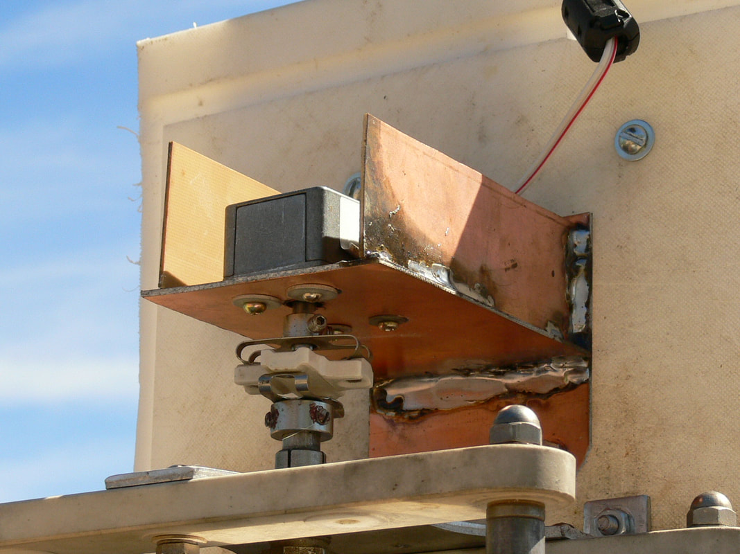
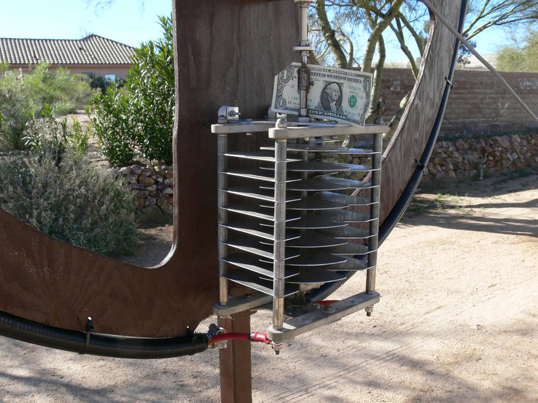
Close up of Butterfly Capacitor and DC Motor Drive.

Remote DC tuning motor ,mount and drive.
Picture
Picture
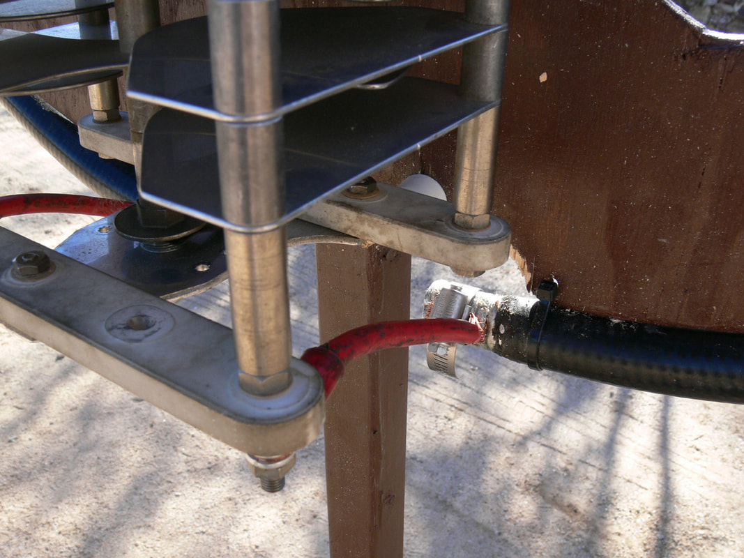
Slot cut into 7/8 heliax ends using grinder with cut off wheel.

Insulation between Center Conductor and Outer Shield removed using Drumel tool with Router Bit.
Picture
Picture
Copper Strap inserted into slot in Heliax Cable. Center Conductor and
shield were soldered to copper strap. Other end of copper strap was bolted to Butterfly
Capacitor.

Phase 3 Mono Band Loop complete.
Picture
How well does it work?

The Magnetic Loop has a figure 8 Radiation Pattern in the plain of the loop with very sharp nulls when turned perpendicular to station being worked. In a recent test a local station was receiving me 15db over S9 when turned in the plane of the loop and when turned perpendicular I was received at noise level and unreadable. When turned to favor a station the loop receives and transmit equal to my Gap Titan DX Vertical.

Stations in Europe, South and Central America and throughout the US have been worked with gratifying signal reports.

Would YOU like help building YOUR own Magnetic Loop Antenna

Submit your request

Understanding Pattern and Polarization of Electrically Small Loop Antennas
by Gary, KD8ZWS

The radiation pattern of a small loop is the same as that of a small dipole positioned perpendicular to the plane of the loop and located at the center of the loop as indicated in Fig. 1a. The resulting 3-D radiation pattern is shown in Fig. 2.

The loop antenna displayed at the March GVARC meeting was in a vertical plane, so the pattern in Fig. 2 would need to be rotated such that the z-axis in Fig. 2 lies in the horizontal (i.e., x-y) plane. In that orientation, the azimuthal pattern will be directional with deep nulls in two opposing directions.

The polarization of the small loop is determined by the orientation of the radiated electric field vector traveling in the direction of pattern maxima, which is any point in the horizontal (i.e., x-y) plane in Fig. 2. (The pattern in Fig. 2 is omni-directional in azimuth.)

What, then, is the orientation of the electric field vector in Fig. 2 if the pattern is that of a small loop?
Answer: the electric field vector will be horizontal and thus, the polarization will be horizontal.
But, the dipole in Fig. 2 is vertical, so shouldn’t the polarization be vertical?
No, because the electric field vector must be in the same plane as the loop.
Why? For several reasons:

First, electric field lines begin and end on electric charges on the loop. So, in the horizontal plane, the electric field vector is in the horizontal plane,

Secondly, there is a constitutive relationship in electromagnetic theory, J = σ E where J and E are vectors representing the current density J on the loop and E representing the electric fieldjust outside the surface of the loop conductor, and σ is the conductivity of the loop conductor. Since J and E are vectors (the bold indicates they are vectors), we conclude that E must be in the same direction (i.e., orientation) as J and thus the polarization must be horizontal in Fig. 2.

Thirdly, the correct dipole to use in Fig. 2 to represent the loop performance is not an electric dipole but a magnetic dipole. In Fig. 1a, note that the magnetic current is denoted Im and has two arrow heads, not one as in Fig. 1b where the current is an electric current, Ie. Note also that the electric and magnetic fields of the electric and magnetic dipoles are interchanged as Figs. 1a, 1b and Table 3-1 indicate. In the electric case of Fig. 1b, the E field is in the plane of the paper whereas in the magnetic case of Fig. 1a the electric field is perpendicular to the plane of the paper. Thus the polarization in Fig. 2 must be horizontal.

However, the polarization of the loop antenna displayed at the March GVARC meeting was vertical since the plane of the loop was vertical.


Do magnetic dipoles actually exist.?
No, and neither do magnetic currents and magnetic charges. But the small loop of electric current replicates the performance of the small magnetic dipole making the magnetic dipole a good model for the small loop of electric current.


Picture

Phase II ~ Progress as of March 13, 2019

Picture
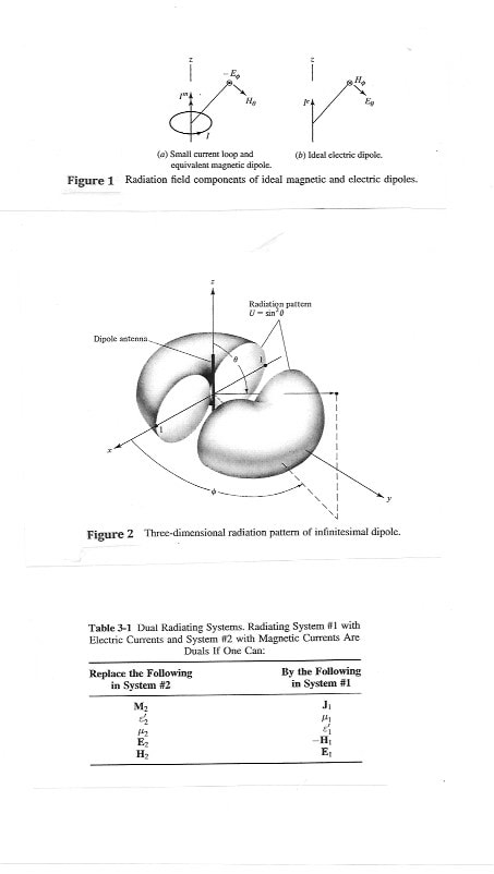
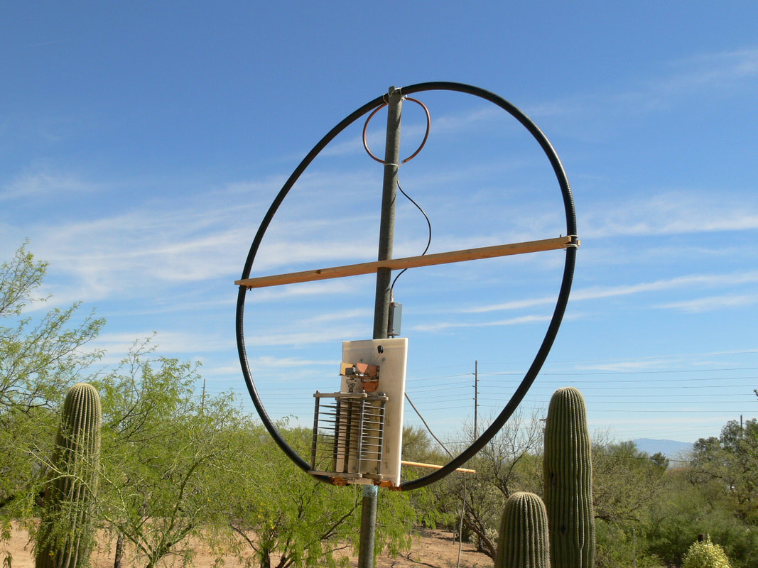
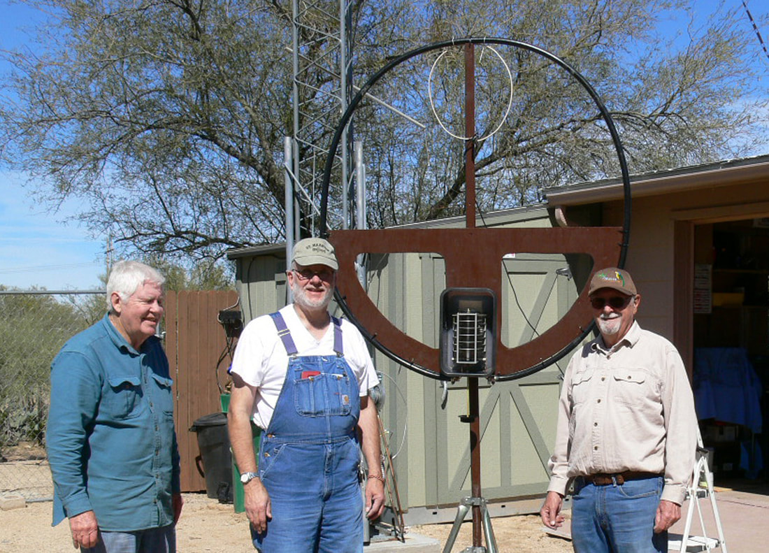
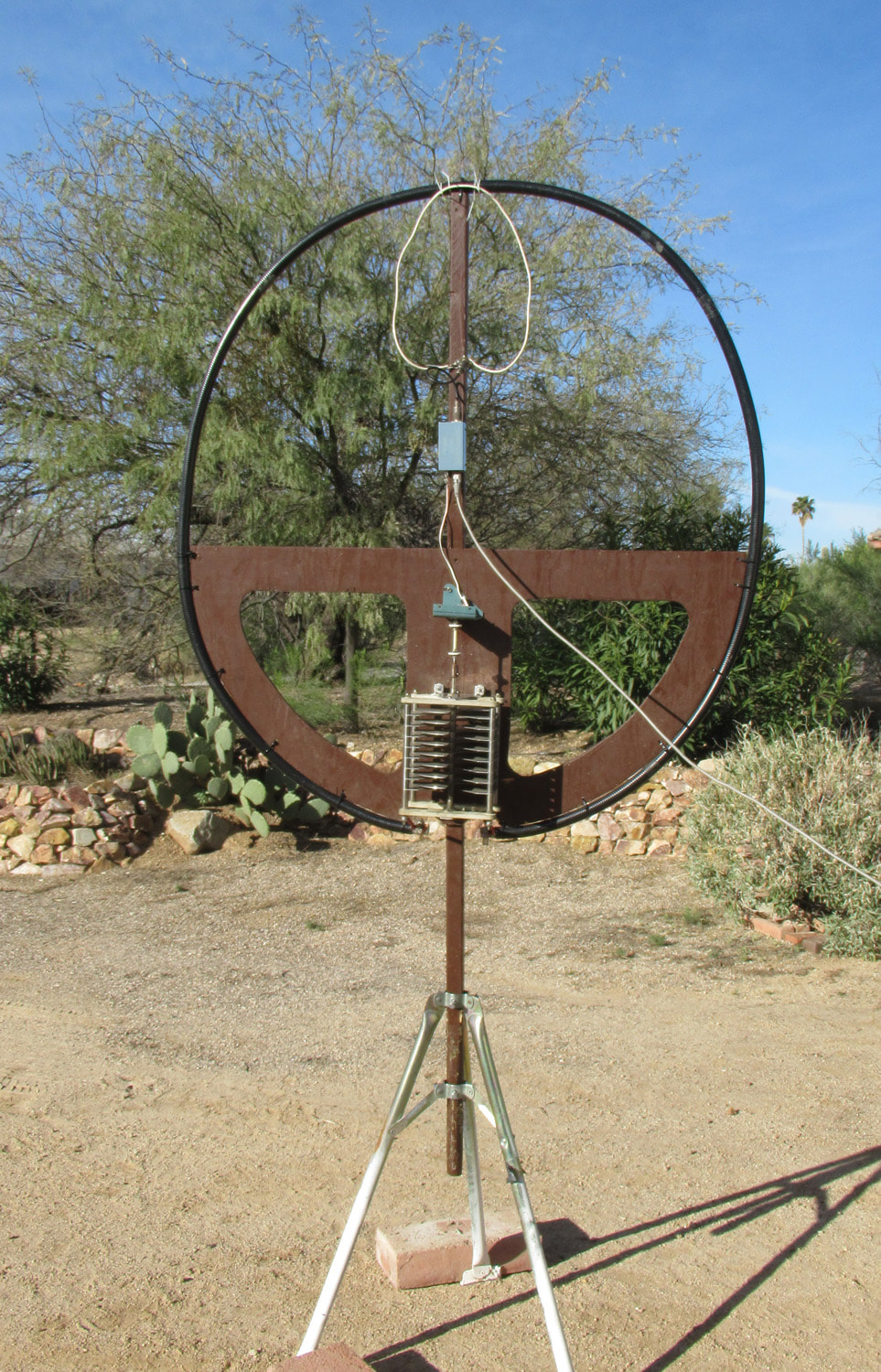
Magnetic Loop project members Roger, W5IP, John, KL7CY, and project leader Bruce, K3BAT. A TV tripod and a wood mast were used for support. For low electrical resistance a 13 foot piece of hardline was used for the loop. A piece of plywood cut out to reduce wind resistance was used for the mount with the loop tie wrapped to it.
The butterfly capacitor Bruce located. This type of capacitor increases the voltage rating to 13,000 volts by using large spacing and structured as two capacitors in series.
Picture
Picture
The very high voltages require adequate capacitor isolation.
Very large currents in the neighborhood of 60 amps require large low resistance connections.
Picture
Picture
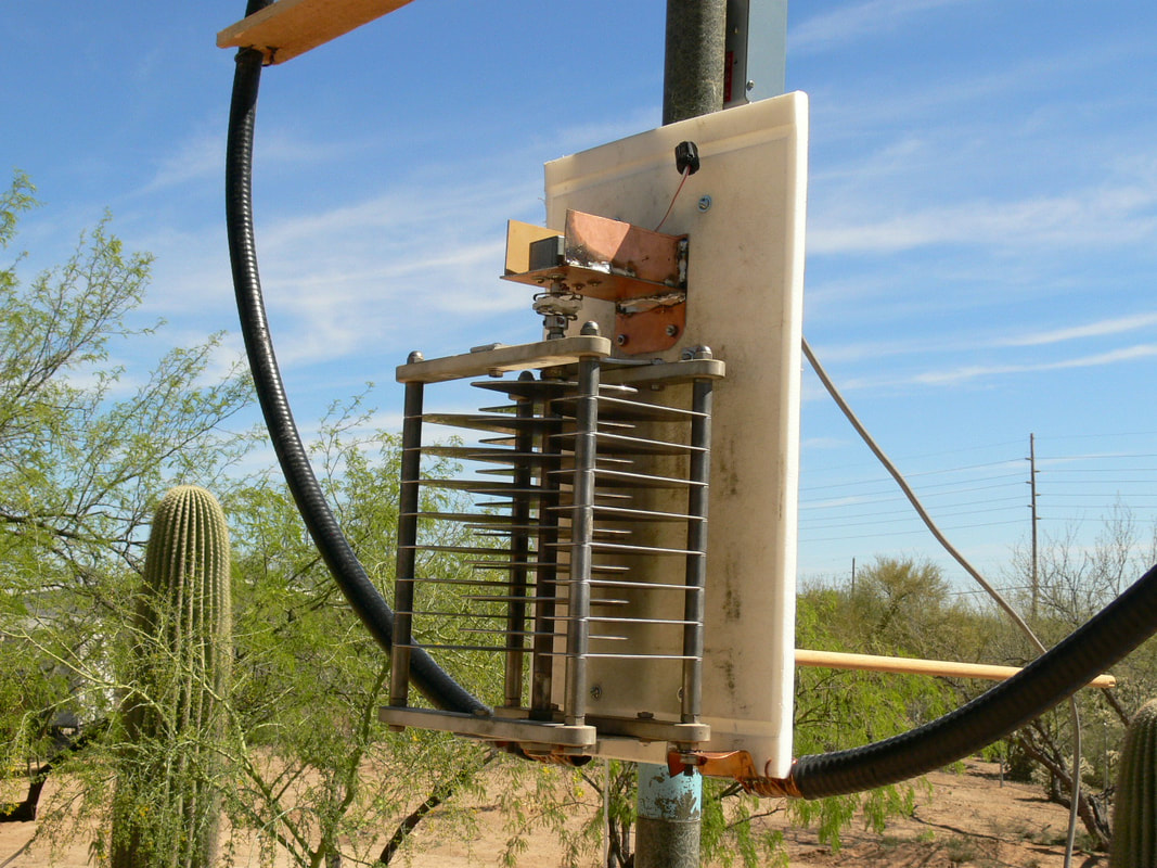
Bruce with the 3rd iteration of the loop showing the current motor drive in place. The coupling loop is also visible and is presently bent out of shape to reduce the amount of coupling,
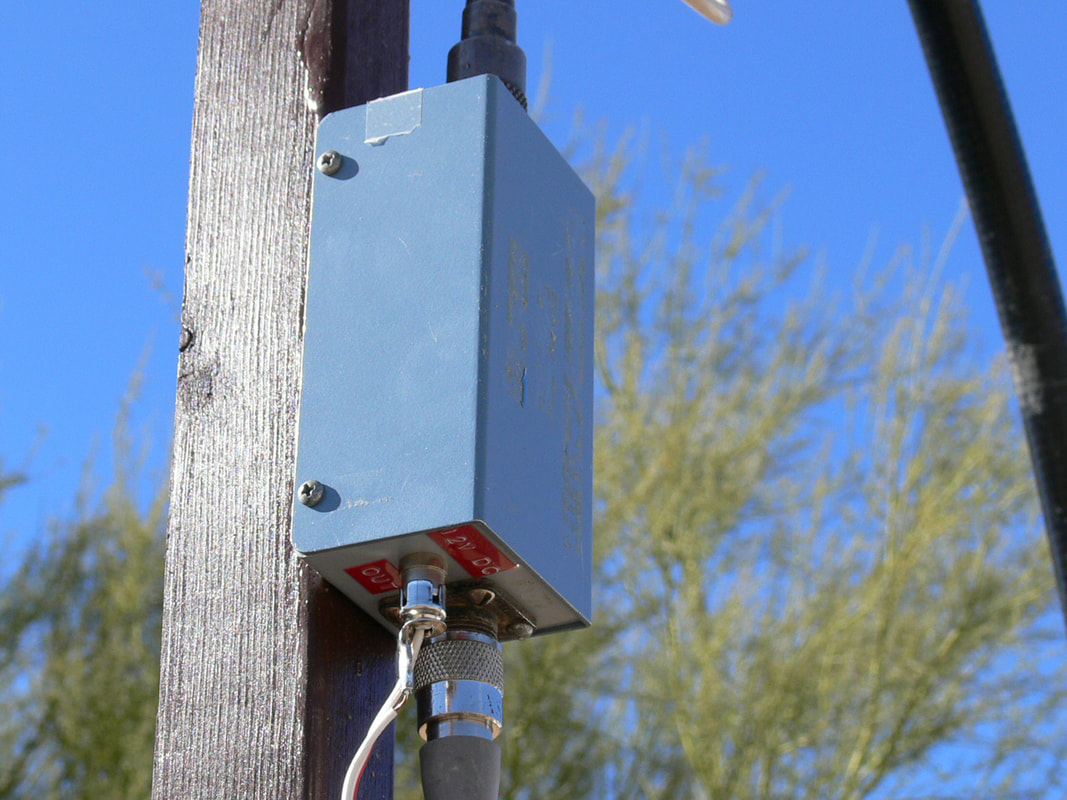
The home brewed bias T unit used in early versions of the loop to transmit DC to the tuning motor. The final remote tuning system is still being trialed.
Picture
Picture
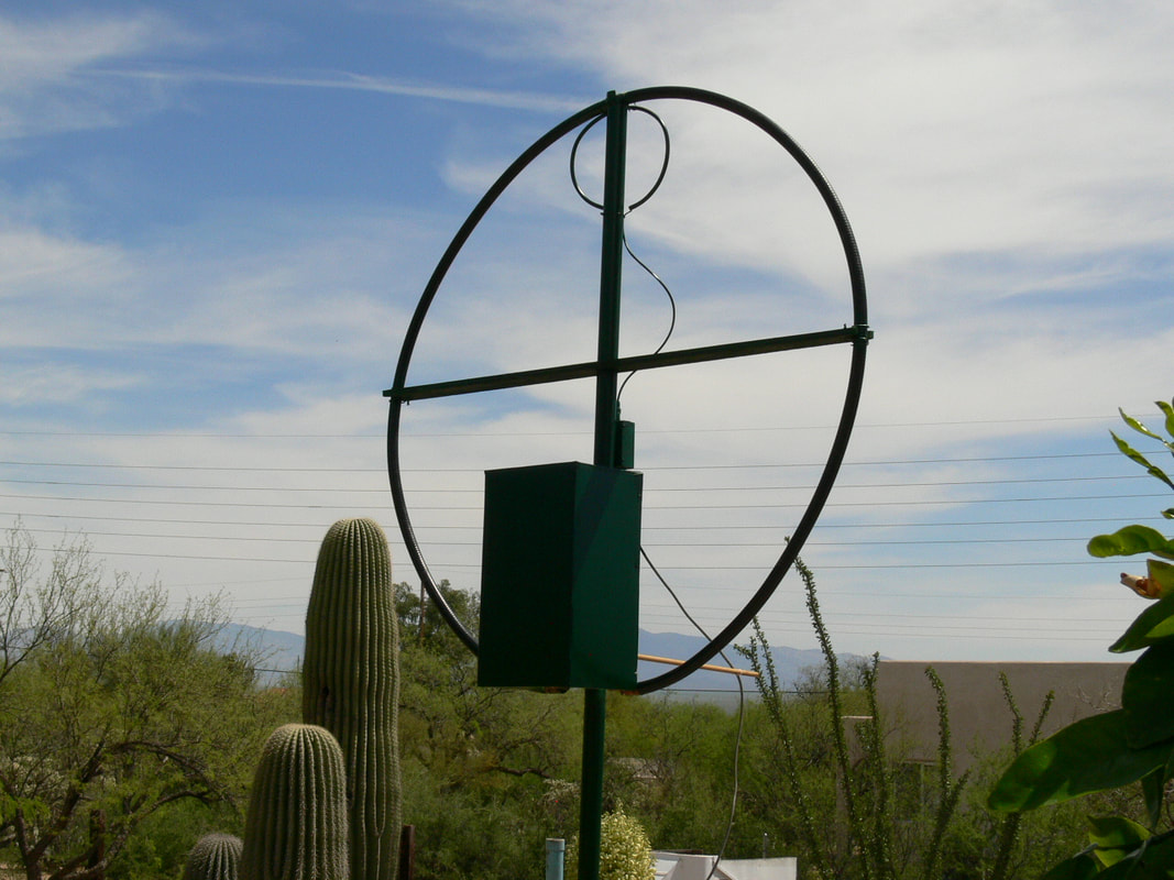
The proposed tuning controller under construction. A revised drive system that removes most of the mechanical slop and a new pulsing DC driver should create more useful tuning steps.
The results of an AIM 4170 scan showing SWR in red, impedance differential in purple and impedance magnitude in green. The 2db bandwidth is about 50kHz as was expected.
Picture

The Plan

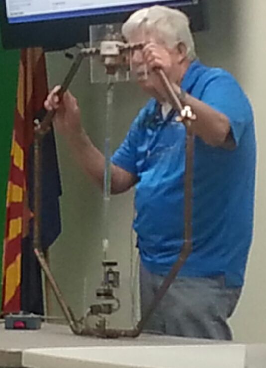
Prototype loop made from 7/8" heliax
Picture

Picture
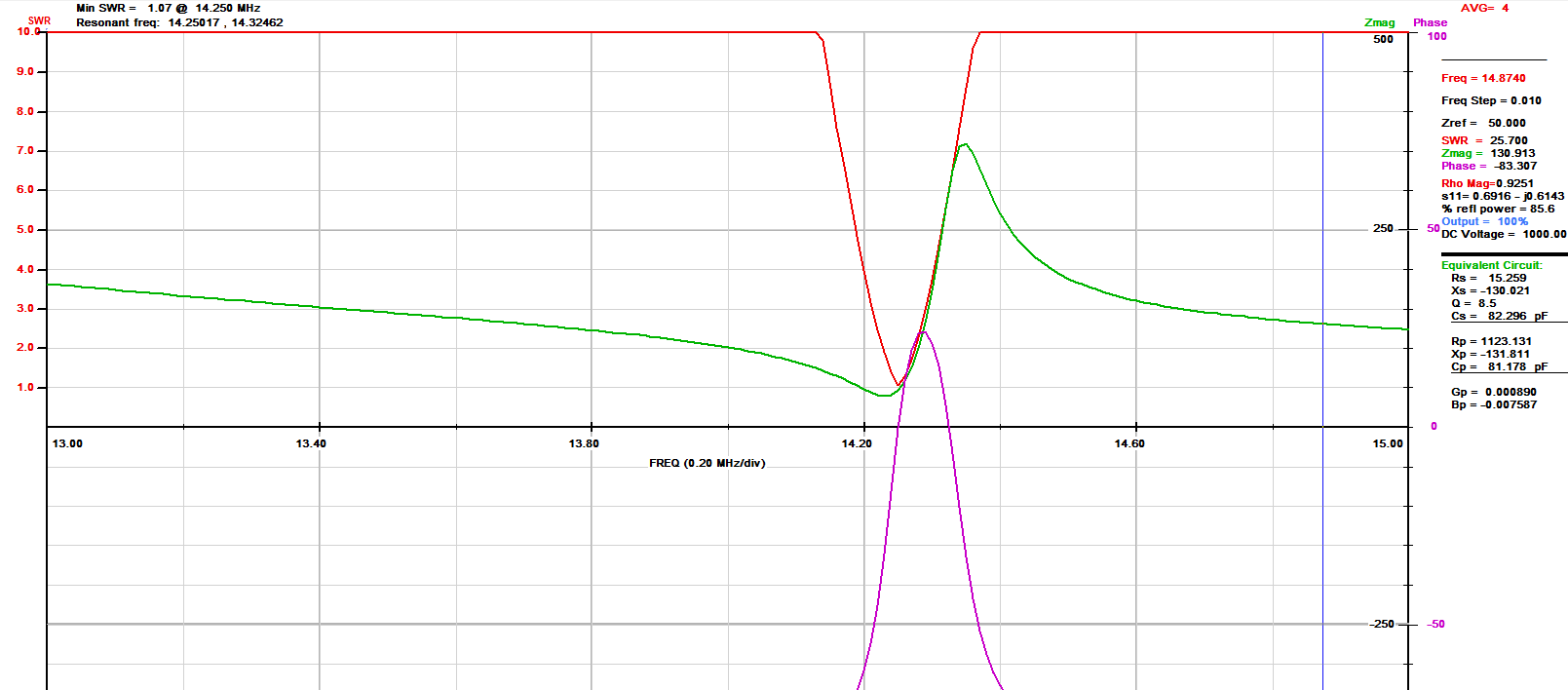
AIM scan of K3BAT's loop on 20 meters.  The red line is SWR

Magnetic loop Antenna Meeting Summery.The Scheduled meeting was held at the home of Bruce Tewksbury K3BAT.

The advantages and disadvantages of the Magnetic Loop Antenna concept were outlined.

Two loops built by Roger Johnson K5IP and a MFJ 1786 donated by Craig Thompson WA3UFY were reviewed. Thanks Roger and Craig. The discussions progressed into Magnetic Loop Antenna construction techneques  and a program found on line at (66pacific.com) that helps design a good working  Mag loop antenna .
The following specifications for our prototype antenna were determined.
1 - Single band 20 meter  ( 17 meter possible ).
2 - Must be usable with 100 watt transceiver at full power.
3 - Hi Voltage Tuning Capacitor.   Requires further study.
      A -  Home Brew or Commercial Butterfly Capacitor.
      B -  Commercial Vacuum Capacitor.
4 - Loop Constructed with 3/4” Copper Tubing. Shape requires further study.
      A - Tube bent into continuous Circle.
      B - Octagon - Plumbers Delight Construction.
      C - Multiple copper loops soldered side by side.
      D -  Loop Diameter 4-5 feet. ( larger loop give better performance.)
5 - Connection loop to transceiver. Requires further study.
     A - Conventional Coupling Loop 1/5  Dia. of Mag Loop.
     B - Gamma Match.

The tuning capacitor in prototype will be adjusted for resonance by hand ( no remote tuning ) to keep cost and complexity down. After confirming performance of loop, remote tuning hardware can be developed, built and attached to prototype.

Everyone at the meeting participated and the meeting very productive - 
Participants were:
Bruce Tewksbury K3BAT  Project Leader,  Roger Johnson K5IP,  Ken Van Horn KE7VH, Joe Pinter KK7DB, Tom Roselund W0MOT, Don Thompson, Ed Toal N9MW, Beetle Baily K7GSB, John Lynn KL7CY
                           Thanks to all
Picture
"Here's a group of GVARC members lead by Bruce, K7BAT discussing loop antennas. Several of the members will be building loops with the assistance of Bruce and Roger, K5IP.  The meeting was held February 5th at K7BAT's QTH.
Picture
  • Home
    • Repeater Info
    • OUR Web SDR
  • Projects
    • 13.8 Volt Load
    • Antenna Ideas
    • Antenna Construction Ideas
    • Dummy Load
    • Past Projects >
      • Organization
      • RFI Mitigation >
        • Direction Finders
      • 2 Meter Gallery
      • Vertical Flagpole
      • Magnetic Loop
      • Wire Antennas
      • SDR Dongles
      • On the Ground Loop Antenna
  • Activities
    • Calendar
    • NETS >
      • Sunday - Two Meter Net
      • Tuesday - Oatmeal Net
      • Thursday- N7GV Simplex Net
      • Wednesday - Snow Bird Net
      • Inactive Nets >
        • Monday - DMR Net
    • Contests >
      • Winter Field Day
      • 7qp
      • Field Day
      • Arizona QSO Party
    • Social Time Out >
      • Wednesday - Breakfast
      • Thursday Evening Dinner
    • Picnics
    • Special Events
    • Titan Missile Museum
    • Driveouts
    • Road Cleanup
    • Parks on the Air
    • HamFest 2025
  • About
    • 2025 Board Members
    • 2025 Committees
    • Meeting Minutes
    • For New Members
    • Get Help
    • Ham Radio Sites
    • Classes & VE Testing
    • CW Interest
    • Ready, Set, Go Info >
      • Ready, Set, Go
      • Your Go Kit
      • My Alerts
    • Donations of Radio Equipment
    • History
    • Gallery
    • GVARC Certificates
    • EchoLink
    • BaoFeng HTs
    • Contact Us
    • We belong to ARCA
    • Miscellaneous >
      • Emergency Plan
      • Links
      • Technical Blog
  • Members
    • Ham Gear for GVARC Members
    • Current Roster
    • GVARC Logo Items
    • Inventory
    • Members We Honor
    • Name Badge Request
    • DMR Info
    • Win System
    • Member Profiles