GREEN VALLEY AMATEUR RADIO CLUB
  • Home
    • Repeater Info
    • OUR Web SDR
  • Projects
    • 13.8 Volt Load
    • Antenna Ideas
    • Antenna Construction Ideas
    • Dummy Load
    • Past Projects >
      • Organization
      • RFI Mitigation >
        • Direction Finders
      • 2 Meter Gallery
      • Vertical Flagpole
      • Magnetic Loop
      • Wire Antennas
      • SDR Dongles
      • On the Ground Loop Antenna
  • Activities
    • Calendar
    • NETS >
      • Sunday - Two Meter Net
      • Tuesday - Oatmeal Net
      • Thursday- N7GV Simplex Net
      • Wednesday - Snow Bird Net
      • Inactive Nets >
        • Monday - DMR Net
    • Contests >
      • Winter Field Day
      • 7qp
      • Field Day
      • Arizona QSO Party
    • Social Time Out >
      • Wednesday - Breakfast
      • Thursday Evening Dinner
    • Picnics
    • Special Events
    • Titan Missile Museum
    • Driveouts
    • Road Cleanup
    • Parks on the Air
    • HamFest 2025
  • About
    • 2025 Board Members
    • 2025 Committees
    • Meeting Minutes
    • For New Members
    • Get Help
    • Ham Radio Sites
    • Classes & VE Testing
    • CW Interest
    • Ready, Set, Go Info >
      • Ready, Set, Go
      • Your Go Kit
      • My Alerts
    • Donations of Radio Equipment
    • History
    • Gallery
    • GVARC Certificates
    • EchoLink
    • BaoFeng HTs
    • Contact Us
    • We belong to ARCA
    • Miscellaneous >
      • Emergency Plan
      • Links
      • Technical Blog
  • Members
    • Ham Gear for GVARC Members
    • Current Roster
    • GVARC Logo Items
    • Inventory
    • Members We Honor
    • Name Badge Request
    • DMR Info
    • Win System
    • Member Profiles

Titan Missile Museum
and
the Discone Antenna

Picture
GVARC often uses the Titan Missile Museum's Discone Antenna for a Special Event. 

  • How to use the Discone Antenna
  • Lighting of the Discone
  • Input from Marty Greene
  • Input from Rodger McIntyre
  • Technical Facts about the Discone

Check out the slideshow from some of the times we have used the antenna.  Below is a slideshow of some of our favorite photos of the antenna and photos taken from the top of the antenna.

Picture
Titan Missile Museum
Discone Antenna


The nearly 80 feet tall Discone was built by Collins Radio Company in the early 1960s and installed at its present location becoming operational 15th of July 1963 by the USAF until the site was deactivated in 1982. The antenna, since then, had been used only a few times by the Green Valley Amateur Radio Club for special events. Since 2007, the antenna has been used on a continuous basis by the Green Valley Amateur Radio Club and HAMS from around the world.
To use this Antenna
  • Go to the Titan Missile Museum Visitors Center and ask them for the sign-in book for the Discone Antenna
  • Read the instructions and sign their sign-in book.
  • Drive your vehicle to the overflow parking lot on the southwest side of the antenna.
  • There you will find an electrical "fuse" box mounted on a steel post at the curb.
  • Open the box and roll out the RG-58U coax.
  • There is a PL-259 connector on the end of the coax.
  • Attach the connector to your rig.
  • Have fun!
We have been asked if it is possible to park your car close by and if we have a table etc. As they say, a picture is worth a thousand words.
But, when museum closes you have to leave.

Note
The elevation at the site is about 2,900 feet above sea level.
Coordinates:
N 31° 54'
W 110° 59.9'
Discone antennas are a no gain broadband band antenna. The SWR (standing wave ratio) is typically 2:1 over the full range of 6 MHz to 30 MHz. The antenna, on a windy day, may be electrically noisy due to years of corrosion in all the joints.
If you have questions or information about this antenna we would like to hear from you. Please click to email the club.

DO NOT CLIMB OVER THE BARB WIRE FENCE

PLEASE ROLL UP THE RG8U COAX AND PLACE IT BACK IN THE ELECTRICAL BOX WHEN DONE. This may be your biggest challenge when using this great old antenna.


Picture

Picture
Lowest frequency it would sweep the Discone Antenna was 5 MHz..

73, Mike WA9TKK
3/13/2024


Picture

1/21/2023
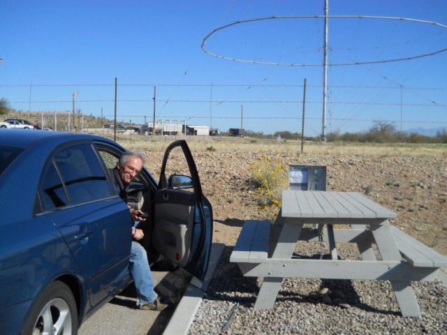
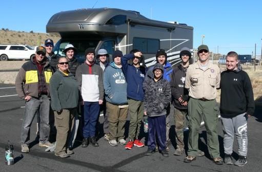
Boyscout Troup 316 and Titan Missile Museum

John Lynn KL7CY and Bruce Tewksbury K3BAT set up a motor home at the Titan Missile Museum on January 21, 2023 to meet with a group of Boy Scouts from Troop 316 in Phoenix.  They discussed ham radio in general, the Discone Antenna, and demonstrated VHF radio using the clubs repeater and HF radio using the Discone antenna at the museum.

Among the group were two scouts and 3 leaders who had Technician licenses. The Titan Missile Museum personal were very enthusiastic about our clubs involvement with the Museum .
Picture
4/22/2022

John Lynn - KL7CY performed a SWR Survey of the Discone antenna  His results are below in a pdf file

His summary was 'Certainly an antenna tuner is needed.' ..Feel free to share as you see appropriate.
John Lynn's SWR Survey of the Discone Antenna
4/17/2021
Frrom Bruce Frahm  via the Webmaster
THANX for the discone use. I used April 16 and 17, briefly. Take my obs with the knowledge 98% of the time I am running 1500W and good antennas. I used my KX3 15W cw.

First off, I had disabled my internal autotuner. I had ~ >4:1 SWR on 40 30 20 17, the bands I checked. SO.... enabled autotune and went at it. Surprised I couldn't get some interest by self-spotting on DX Summit. But did answer a 20M CQ from a WB3 for short QSO. Then skedded hometown (nwKS) K0FJ and K0FW. Worked both, with ~ 579 sigs, on 20 and 30. None of us heard anything on 40. On 17 I heard K0FJ 549.... he ESP heard me. No joy 17 with K0FW. Today 17th I returned and had a nice 30M QSO with a camper near Napa CA... he was ~ 579, I was ~ 449 average with fading but 90% solid. Then worked VE3CX on 20 in Ont QSO Party, with some difficulty. Again, surprised that self-spotting on both bands netted zero QSO.

Due to the high SWR with no tuner I wonder if there is an issue. Anyway, I had fun even though only 7 QSOs. And the museum tour was interesting. TNX 73 K0BJ
From the 'Reflector'

We had heard reports that the discone antenna at the Titan Missile Museum (that we in part maintain and advertise) was not performing well. On March 27 a couple of us performed a VNA scan from the coax termination in the parking lot.  It did not appear to be electrically  problematic so we deemed it usable.  Then some nagging little birdie hinted we ought to check further.

Tuesday, March 30, Tom K7VOA, Ron AA7RP and I N9MW revisited the site to make measurements from the base of the antenna.  Tom and Ron got there first and discovered that who ever did the weed whacking had no appreciation for our feedline.  The outside jacket and some of the shielding had been torn off.  Since the inside conductor of the coax was still in tact explains why previous test readings sort of looked normal.

April 1 Tom and I replaced the damaged section of coax and placed additional protection over the wire.  The VNA scan shown here and antenna analyzer tests on the coax between the antenna and parking lot indicate the system should again be performing.

Our observation also is that we may need to do more testing as tests on the feed line and the VNA scan of the antenna appear marginal.

Ed N9MW
4/1/2021
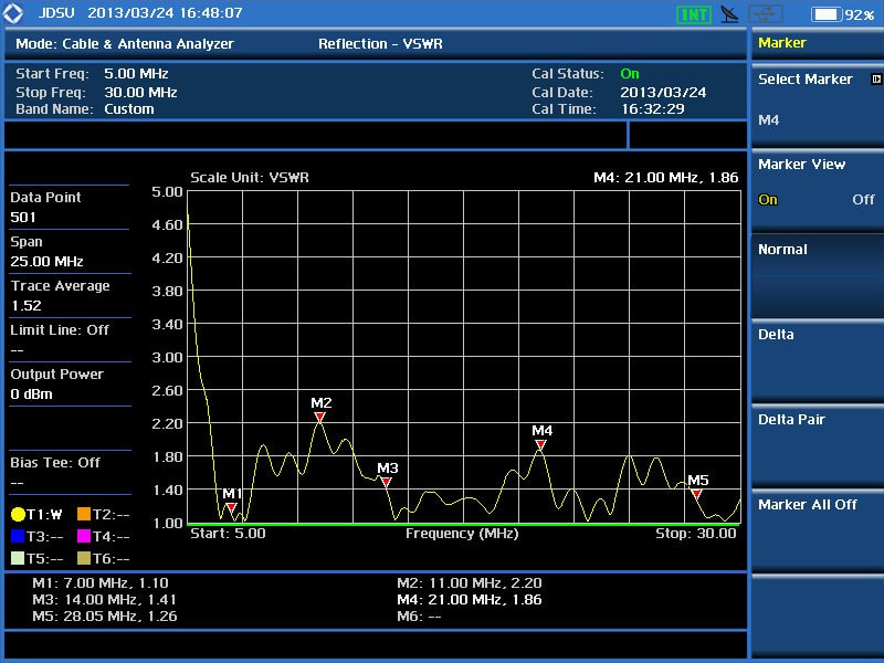
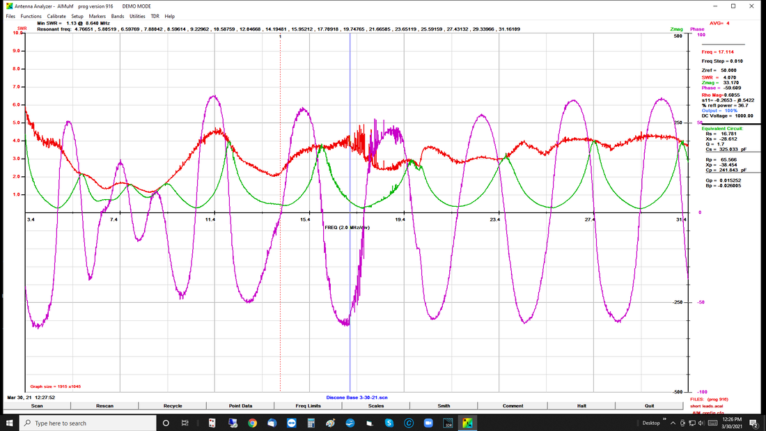
The graph is a VNA scan from 3.4 to 31mHz of the Titan Missile Museum discone antenna performed with an AIM 4170 on 
March 30, 2021.

  • The test was performed at the coax termination at the base of the antenna.
  • The purple line is the measured difference in reactance phase.
  • The green line shows the actual reactance measured.
  • The red line is the resulting SWR.

It can be seen the antenna has an unusually low SWR across the entire range tested. However, many present day transceivers will start doing a power protection (reduction) at a 2 to 1 SWR so the full benefit of this antenna won’t be realized without some additional matching at the feed point.

N9MW

Picture
Picture
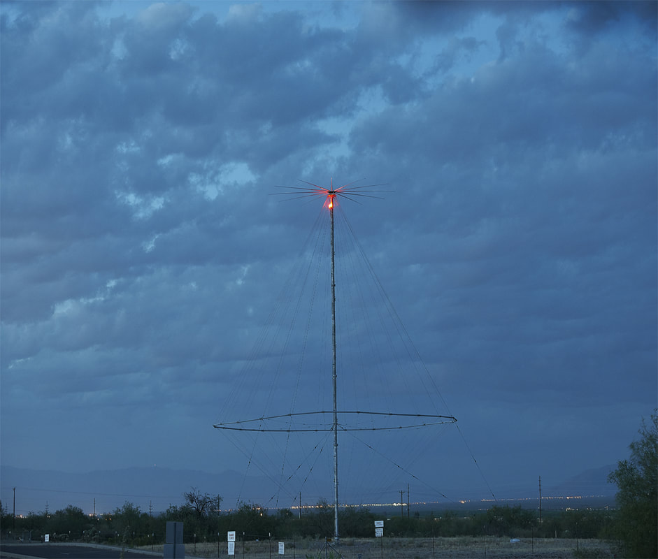
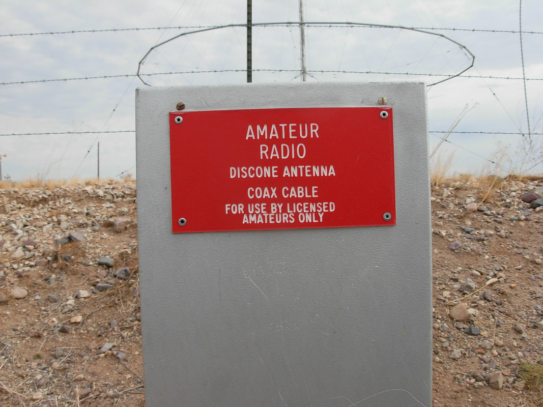
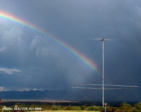
On January 26, 2017, the Green Valley Amateur Radio Club and Wallen Communications out of Tucson, Arizona put in another new RG-213U transmission line and re-lit the obstruction lights on the Collins Discone antenna at the Titan Missile Museum in Sahuarita, Arizona. We are working with the Titan Missile Museum to keep the lights lit. It is in working order and ready for amateur radio use.

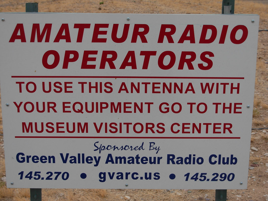
Ham radio operators are welcome to sign in at the Titan Museum front desk between 8:45am and 4:30pm seven days a week and use the Discone antenna. The Discone now operates on 40, 20, 17, 15, 12, 10 and 6 meters.

Please abide by the rules of the Titan Missile Museum. Enjoy yourselves and make a lot of QSO's.

73's

Tom Lang K7VOA


These are comments and information from others about the Discone antenna.

On 11/7/2019

On a recent visit to Tuscon, I was able to operate from the discone antenna. It was really fun. Thanks to the club members that keep the antenna working.

73
Dick - KC3EF
On 2/11/2019 12:34 PM, Marty Greene wrote:

Greetings GVARC! 

As a former Titan II crew member (1970-1980) and as a new Ham operator (KN4NYI – Amateur Extra) your site, the museum, and the ability to plug into the antenna are all big favorites, and will make up a dream camping vacation. (even though it is a long way from the middle of South Carolina!)
 
I’ve been doing some research on the HF antenna, and discussing it with others on the “100 Watts and a Wire” board on FaceBook.  There are some differences of opinion, and differences in wording.  Here’s what I’d like to point out:

  1. The Titan II Handbook, from the museum, authored by Chuck Penson, describes the antenna as a “discage.”  This was a coined word, made up from the combination of a “discone” at the top, made of radials, and served from 6 to 30 MHz.  The lower portion, the big “Christmas tree” was a folded cage monopole, and served from 3 to 6 MHz.  The selection of either portion was done at the Deputy’s console in the control center.  The “discage” was the whole thing, unique to this total design, but the “discone” actually refers to the top portion.
  2. Your video of the work you did in 2017 actually shows the feed box.  It shows Lloyd and Tom working “in the dirt,” and you can see two leads coming into the junction box from the antenna.  The other lead, that you have marked “Guess” at 8:45 in the video, is actually the feed from the lower portion, the folded cage monopole. Now it may very well be that the lower portion served as a counterpoise or ground plane when the top portion was in use.  But nevertheless, two feedlines, from two antennas, were presented to the Launch Control Center, both from a combined antenna structure.
 
I was an electronic tech, and even spent my last few years at the 381st SMW at McConnell AFB, KS, as an Engineering Technician.  That’s when I REALLY got to chase wiring diagrams!
 
If you search on the words discage antenna, you’ll see images of several variations, and several of yours, your club, and your picnic table with plug-in!
 
73 from South Carolina!  I hope to visit you soon!
 
Marty Greene


Greetings GVARC

After viewing your web page, I could not help but want to contact you and make a comment about the HF discone antenna you have displayed and use in your club activities. Please bear with me as I jog my memory a bit, going back about thirty years. My name is Rodger McIntyre and I was stationed at Davis-Monthan AFB from November 1975 to December 1978 in what was first, the 803rd Communications Squadron, later redesignated as the 390th Communications Squadron. I was assigned to the HF-SSB/UHF maintenance unit. I was enlisted in AFSC 30454-1 or, GROUND RADIO EQUIPMENT REPAIRMAN, having trained at Keesler Technical Training Center, Keesler AFB, MS from January to October 1975. The "-1" suffix was designation for the Titan II Ground Radio specialty. The 30454-5 designated group were trained for and bound to Minuteman sites.

Anyway... our HF group maintained a rack of gear which resided one floor below the complexes command center. The HF "rig" was a Collins 9000 series exciter, 2 to 30 mHz AM, USB and LSB capable along with a 250W RF amp, capable of 1000W peak in the sideband mode of operation. The equipment had several auxiliary pieces, of course a very hefty power supply for the RF amp, and at the output, a coax switch operable from the remote HF control panel on the launch control level at the DMCCC's duty station.

The RF output was normally fed to the "soft" or surface (discone) HF antenna. During PM maintenance, the RF output would be switched to the stowed or "hardened" HF antenna for a radio check as well as a check of the soft antenna. The hardened antenna was designed for use once or perhaps twice following, and in the event of a "hit" as a hit would cripple or destroy the soft antenna.

The hardened antenna was controlled by and had to be extended to tune it to the selected frequency. Once the operating frequency was selected, the hardened antenna would essentially "auto tune" via a syncro controller module, mounted within the HF control panel. It's vertical up-down behavior could be loosely compared to "up-periscope" and "down-periscope" on a submarine. The hard antenna's mechanical drive was a series of guide rollers driven by automobile-size tires surrounding the telescoping mast, which were coupled to a drive train, subsequently driven by two 440VAC three phase industrial size motors, about two-hp. Myself and other ground radio repair techs maintained all of this equipment, performing periodic PMs on the transmitter and on both the hardened and soft antennas.

The rack was inspected on a 28 day PM cycle and I believe the antennas were maintained on a 60 day or similar PM interval. Any rack equipment that failed to meet minimum specs was pulled or R&R'ed and went back to the shop where we performed bench electronic troubleshoot and repair to the component level, along with RF re-alignments and certifications to return the defective unit to serviceable condition.

The hardened, stowed antenna required fairy involved maintenance with it's launch and stow drive apparatus, but the soft antenna maintenance was mostly coax cable and RF connector inspection, cleaning and replacement of RTV as needed. The transmitter's VSWR check was the main indicator of the antenna's ongoing RF cable integrity along with a thorough visual inspection of the assembly, especially the non-metallic stand-offs supporting and spacing the radiating elements from the frame.

Best Regards,
Rodger McIntyre
Tucson, AZ


..
  • Home
    • Repeater Info
    • OUR Web SDR
  • Projects
    • 13.8 Volt Load
    • Antenna Ideas
    • Antenna Construction Ideas
    • Dummy Load
    • Past Projects >
      • Organization
      • RFI Mitigation >
        • Direction Finders
      • 2 Meter Gallery
      • Vertical Flagpole
      • Magnetic Loop
      • Wire Antennas
      • SDR Dongles
      • On the Ground Loop Antenna
  • Activities
    • Calendar
    • NETS >
      • Sunday - Two Meter Net
      • Tuesday - Oatmeal Net
      • Thursday- N7GV Simplex Net
      • Wednesday - Snow Bird Net
      • Inactive Nets >
        • Monday - DMR Net
    • Contests >
      • Winter Field Day
      • 7qp
      • Field Day
      • Arizona QSO Party
    • Social Time Out >
      • Wednesday - Breakfast
      • Thursday Evening Dinner
    • Picnics
    • Special Events
    • Titan Missile Museum
    • Driveouts
    • Road Cleanup
    • Parks on the Air
    • HamFest 2025
  • About
    • 2025 Board Members
    • 2025 Committees
    • Meeting Minutes
    • For New Members
    • Get Help
    • Ham Radio Sites
    • Classes & VE Testing
    • CW Interest
    • Ready, Set, Go Info >
      • Ready, Set, Go
      • Your Go Kit
      • My Alerts
    • Donations of Radio Equipment
    • History
    • Gallery
    • GVARC Certificates
    • EchoLink
    • BaoFeng HTs
    • Contact Us
    • We belong to ARCA
    • Miscellaneous >
      • Emergency Plan
      • Links
      • Technical Blog
  • Members
    • Ham Gear for GVARC Members
    • Current Roster
    • GVARC Logo Items
    • Inventory
    • Members We Honor
    • Name Badge Request
    • DMR Info
    • Win System
    • Member Profiles