Dummy Loads
Almost all radio transmitter tuning and testing requires a test termination usually at 50 ohms. You will find that sometimes a very accurate load is required with many available “dummy loads” failing the test at high frequencies or various power levels. And some of them are more expensive than one would expect. I came across an answer when I heard about thick film resistors. In this project I use two Ohmite 100 watt 100 ohm resistors in parallel providing a very accurate 50 ohm load at outputs over 100 watt, perhaps up to 200 watts for short time periods.
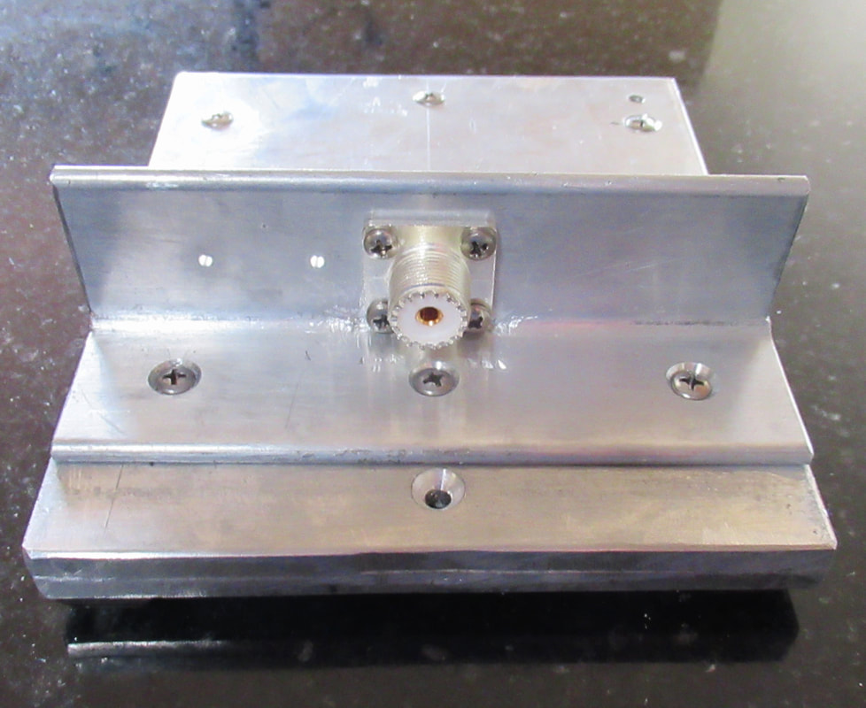
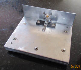
There’s nothing very pretty about this unit. It is constructed of scrap aluminum plate donated by a local Club member, a chunk of aluminum angle, some stainless steel hardware and a UHF connector. (Thanks to all of you who offered material) A 50 ohm BNC or N connector should be used for accurate results above 2 meters. In this case several small pieces were laminated together to create sufficient mass to dissipate heat using SS bolts, tapping the receiving plate so no nuts were used, the heads are countersunk and heat sink compound used after cleaning the adjoining pieces.
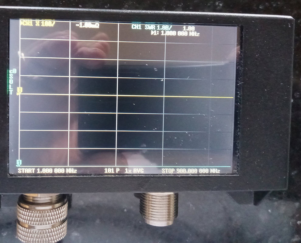
The pictures show the simple construction front and back. A housing could be placed over the resistors for protection, but is not really necessary. I apologize for the fuzzy picture of the VNA scan. However, you can plainly see the blue trace SWR is 1 to 1 from 1.5 mHz to 900 mHz and the yellow trace impedance is flat 50 ohms.
This is a very useful tool for any shack that is easy to build at a low cost. The resistors are roughly $10 each, the rest is scrap box material.
N9MW 3-16-23


